|
I/O connectors.
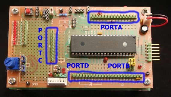
Several groups of connectors 2.54 allow access to the processor pins.

There is a set of connectors for each port, interspersed with pin devoted to 'power. Screen printing clearly indicates the various
functions.
Below you can see the connectors
PORTB and PORTD, accompanied by several supply pins. This allows you to connect to the I / O external modules of all kinds.
The screen printing on the printed circuit allows you to easily identify each connection.

Near the connectors are available as twin rows of holes to add additional connectors or various components and thus allow further
expansion.
The connections on the board between the pins of the processor and the bank of LEDs or potentiometer, or to external modules, can be made with ease with cables with female connectors at both
ends.
These cables can be self-made or recovered from old PC wiring, but also simply bought ready-made, for example, from the Microchip catalog p / n AC163029
( http://www.microchipdirect.com/)
or
the cable set from Mikroelektronika (http://www.mikroe.com/eng/products/easybuy/
).
Seriale connection.
In general, the pin and
PC6 and PC7 are programmable as input / output of the module UART /
USART.
Given the importance of still communicating with this form in the field of embedded, it will be a dedicated
connector.
 |
The group consists of:
- a 6-pin connector, polarized
- a group of 4 pins
- two low power LEDs
the resistances in series with the LEDs are mounted on removable socket.
The polarized connector (Molex) gives you access to:
- supply (Vdd-Vss)
- PORTC6 and PORTC7, respectively TX and RX of 'USART
- two-pin plugs connected to the group and planned to auxiliary signals RTS / CTS
|
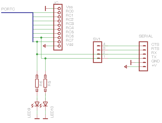
This
is the schematic for the section:
 |
Pins 3 and 4 of the group thorns SV1 can:
- be connected to the I / O processor that the firmware will use as RTS / CTS
- bridged between them for a null modem on 'external adapter
- or simply not used
Even a temporary jumper on pins 1 and 2 of SV1 can be used for a loop test of the operation of the program. |
Experience has also recommended to add two LEDs on the lines of communication with the monitor function: the LEDs will light up when the level of the lines will be high.
In order to disturb as little as possible the status of these lines have been inserted at a very low current LED, capable of igniting even with less than 1 mA, the current that can be supplied easily by both the pin of the micro, both from the side at the level of a logical interface RS2-32 or the
like.
But it is also possible that PC6 and PC7 are dedicated to other uses, so it will be accessible primarily by its connector, in which case you may not need to have the diagnostic LEDs inserted, or you might have connected a device with a very low fan out . This is the resistance in series with the LEDs are mounted on pin removable and can be removed (or changed in value) as required by
application.
You can connect to the SERIAL connector interface modules RS-232, RS-485 but also, using one of the auxiliary pin as a direction.
They will also be connected current loop interfaces, IRDA or any other kind of serial communication treatable by 'USART. The presence of two power pins, you can use the Uniboard powered devices such as Zigbee interfaces serial, Ethernet-to-serial, serial-Bluetoooth, I2C serial,
etc..
 |
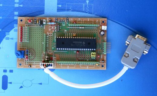
Uniboard to which is connected an RS-232 adapter enclosed in the protective shell of a DB-9 connector.
The jumper between pins 5-6 of the serial connector creates a null-modem connection between the RTS-CTS RS-232 line.
|
|