|
LEDs.
UniBoard have an array of 8 LEDs, accessible by a dedicated
connector.
LEDs are connected to the Vss (GND) and then are switched on by applying a high level to the corresponding pin of access.
 |
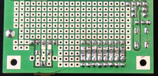
Each LED has a resistor in series; for reasons of space heaters are
smd.
The LEDs are very low current, to which also light up with less than 1 mA.
This makes them suitable not only as output devices, but also in parallel on the lines of I / O such as
diagnostics.
|
The resistors are between 1800 and 2200 ohms. If you want more light, you will use the value of least resistance. Wanting to reduce the current, you can use resistors of greater value: LEDs are lit in a clearly visible even with 0.7 mA or
less.
Potentiometer.
Useful for experimenting with the form AD the presence of a
manually adjustable potentiometer.
It is an element of quality Cermet, linear, connected to a group of 5 plugs to make flexible the most
use.
To use it as a generic source for analog experience, it will be possible to connect pins 1-2 and 4-5 with two jumpers, so as to arrange the supply voltage at the ends of the potentiometer; pin 3 will then be connected to 'analog input wanted .
This system jumpers, however, also allows to connect the potentiometer for example between ground and a reference voltage or to use as an element of a more complex
circuit.
The table summarizes the possible configurations:
| Jumper |
pin |
Funzione |
| 1 |
2 |
3 |
4 |
5 |
|
- |
GND |
Pot. |
Cursor |
Pot. |
Vdd |
Potentiometer free from any connection and accessible
by pins 2-3-4 |
| 1-2 |
GND |
GND |
Cursor |
Pot. |
Vdd |
Potentiometer with a pin connected to Vdd. Accessible
the cursor (pin 3) and the other end (pin 4) |
1-2
4-5 |
GND |
GND |
Cursor |
Vdd |
Vdd |
Potentiometer connected between Vdd and Vss. Cursor
accessible (pin 3). |
 |
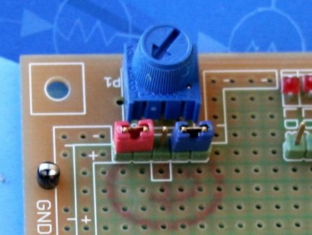
Here's what the potentiometer with the ends connected to Vdd (red jumper) and Vss (blue jumper).
In this way, the cursor is provided to the pin remained free. The voltage will vary between Vdd and Vss, for a direct connection with an input of the ADC module of the microcontroller.
|
For example, cursor connected to RA0/AN0.
If desired, the component side allows you to solder a capacitor SMD, size 1206, between pins 2 and 3 (typically cursor and
ground).
The potentiometer is 10k, well with the maximum recommended source resistance measurements with the AD
module.
Out of curiosity, mounting is not parallel to the plane of the printed circuit board to the potentiometer in the pictures has been chosen to make it easily adjustable by hand the
cursor.
Bredboard area.
Uniboard has an area intended to 'addition of the components that the' user deems
necessary.
 |
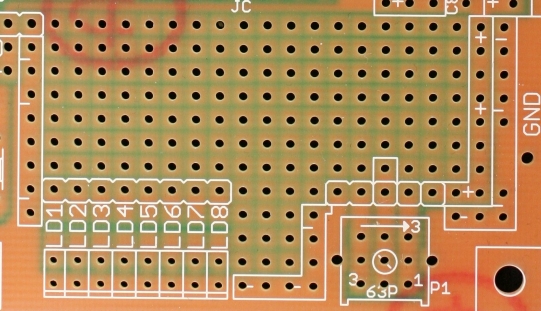
Several holes are connected to the power supply;-side components are identified by screen
printing.
It can be noticed the
mounting area of the potentiometer with a multiple drilling that accepts different
types.
|
 |
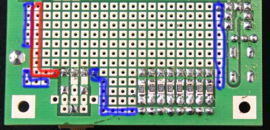
Several holes are connected to Vdd and the ground, to facilitate the 'supply of active components that may find space in' area.
These points are identified in the screen printing.
On the copper side, in the picture are highlighted with blue (ground) and red
(Vdd).
|
The holes are of large diameter and the plots have a good surface. In tandem with
high quality printed circuit board that enables soldering and desoldering components several times and with ease.
|