|
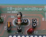
Reset circuits.
The pcb provide the classic circuit with R5, C6 and manual reset button.
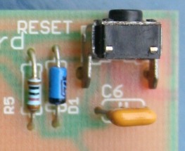 |
The separation with the circuitry ICSP is given by a small Schottky, which can be replaced without problems by a simple resistor 1k.
Provided that you intend to install these parts, since R5, C6 and button can be omitted if you use the MCLR pin as I / O (for the PIC that have this
option).
Or just the only R5 (10 k typical) and is more than enough. |
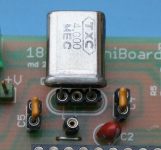
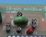
Clock circuit.
You can make clock:
- with quartz (Q1, HC49) with the capacitors (C4, C5, about 27 pF)
- with three-pin ceramic resonators, installed in place of the quartz
- with RC (R7, C5)
- with external oscillators (on RA7)
- with ... NONE (internal oscillator), as many PICs provide.
In this way it is possible to test all the possible options, given that, even if not perfectly ideal, the pins of 'oscillator are reported to the external connector, in order to exploit both external oscillators, both the functions of GPIO pin, programmable as GPIO or output clock / 4 in some PIC.
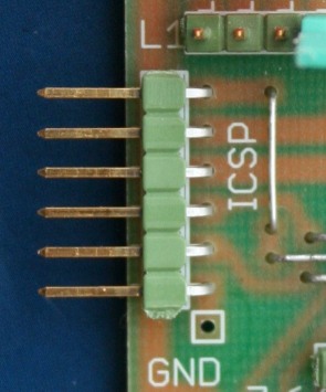
ICSP/ICD:
There's not much to say about this: the J1 connector is expected to engage directly in a Pickit, but you can make a cable adapter for any other tool, such as those that come with an RJ as ICD and REAL ICE; or buy from Microchip appropriate adapters
ready.
 |
Keep in mind that, if the majority of the 18-pin PIC, the connection is used for on-board programming (ICSP), in some models is also active on ICD debug circuit (at the end of 'article contains a table the characteristics of the PIC 18 pin and the possibility of programming / debugging with the tools relative).
In particular it should be noted that the chip with the logic of integrated debugging (eg. 16F88) are the most suitable for the development work, to be transferred then possibly on the final chip.
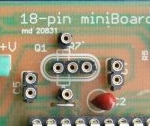
An additional test points can be welded to pick up the signal PGM / spare the PICkit (in the picture you can see the well bore engagement of the
spinet). |
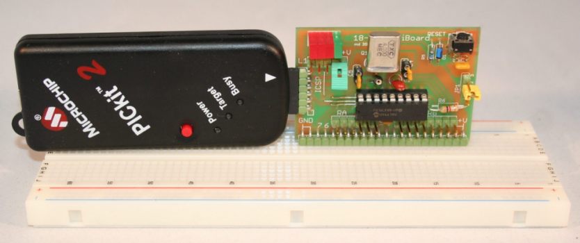
A particular: the position of the connector ICSP has been provided at the correct height to engage in Pickit, which rests on the breadboard without forcing on the connector.
|