|
Breadboard's connector.
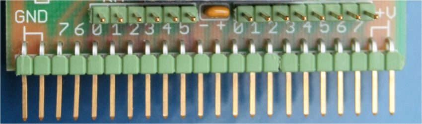
A row of 22 plugs (J2), 2.54, allows you to insert any miniDemoBoard in a breadboard and use a macro component that supports the basic circuit of the microcontroller, requiring only the wiring of additional components of the
'specific experiment.
A pair of start and end is dedicated to the Vss and Vdd. It is, however, essential and the first two and the last two pins may be omitted safely: the board is powered by a pair of middle pins (11 and 12).
The pins PA5: 0 and PB7: 0 are accessible, moreover, with two groups of thorns step 2.54, both to allow additional connections, both to connect them to the LED's on-board.
In addition, the connector is also used in stand-alone mode to connect to other circuits that are made in any way.
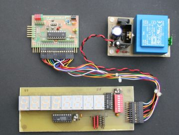 |
In the photo, the 18-pin miniDemoBoard connected to an external power supply and a display controller for counting to 8
digits. |
LEDs.
Can not miss LEDs...
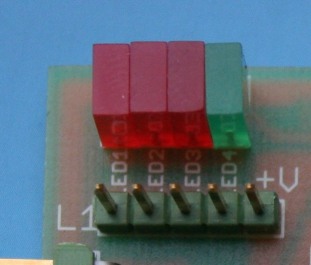 |
Since there was enough space, have been provided LED.
Were chosen LED rectangular 2 x 5 mm, with the cathode to Vss, or to be switched on must be applied a positive voltage (positive logic; V = 1 LED = ON).
Each anode is connected through a limiting resistor to a test point that can be connected to GPIO PIC: This is useful not only to test the minimal Blink-a-LED, but to make certain reporting capabilities without having to wire outside of the
LEDs. |
Connections to I / O are made with short jumper.
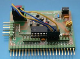 |
In the photo you can see the connections between PB0-PB3 and four
LEDs.
The cables were obtained from the recovery of internal wiring of old PC
enclosure.
They can be made with crimp connectors or AMP Molex, but are also available ready-made, easily found on the
WEB, for example from the same Microchip
(p / n AC163029). |
In the prototype LEDs 1-3 are red and LED4 is green.
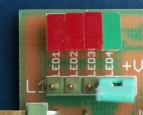 |
The pin on the green LED has been joined by a pin connected to Vdd.
If the LED is not used for anything else, with a simple jumper you can close the connection and use the LED as an indicator of the supply voltage
present.
|
The limiting resistors for the LEDs are smd. welded on the component side. E 'was chosen 1206 Format that allows manual welding without requiring specialized microscope and soldering stations.
The value depends on the current that you want to make to pass in the LED (Tutorial in a series of pages develops this topic); depending on the "hardness" of the LED, of the operating voltage and the desired brightness, the resistance may vary from 470 to 1 kohm. Choosing energy efficient LED you can save energy while having a visibility of LED is well
marked.
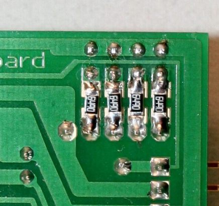 |
In the photo, the group of resistors smd seen from solder side.
In this case it is 1206 from 650 ohm resistors.
The welds were made with a normal stylus fine tip to 18 W..
|
|