|
Do it !
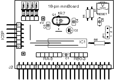
Simple. The following is the image of the single layerpcb (copper side view)
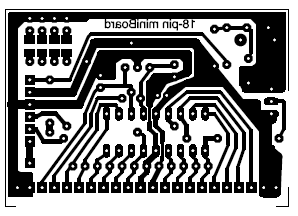
and the component's layout:
 SCALE 2:1
Here
you can download the c.s. in. pdf, scale 1:1.
The only point that may be critical is the group of jumpers in the processor socket, which are close together, but not impossible. And limiting resistors for LEDs that are SMD. However were used components 1206, to which with a soldering iron tip end, it is possible to weld them without a microscope and without
problems.
NOT ALL components must mount: you can install what you think of those who use and add the rest later. For example LED and its strengths, reset button, resistance of RB4, internal test points may be omitted if not required.
In the prototype in the photo were used hooves of the contacts of a tulip for the 'area of
the clock, so as to be able to quickly replace the various components and switch from one oscillator to' another. Of course, if you decide for a fixed type of oscillator, this is
useless.
The PCB is single copper was chosen so to be able to make at home: by photographic moment ago, not having parts critically
thin.
The first prototype, starting from the master, took less than 2 hours to complete; shown in the picture is the final version with solder and screen
printing.
This printed circuit board will fit not only for hundreds of experience, to be used both on the breadboard or as a component of other circuits, but also as a central unit for prototyping.
Totally unnecessary to remember the rules for good soldering: soldering iron with a fine tip isolated, max 20 W, tin 40/60 quality, 1 mm or less (if not new-but-bad solder under Rhos), non-recovered 200
times, etc..
If you think you interchange several times the processor will be required to use a socket with tulip contacts and strictly avoid clogs low
quality.
Components list.
The table shows the 'parts list.
Some components are shown as optional and will depend from 'user insert or less depending of' application choice
| Parte |
Componente |
Funzione |
OPZ. |
Note |
| IC1 |
Zoccolo tulipano 18 pin |
Supporto PIC |
no |
Di buona qualità |
| Q1 |
Quarzo HC49 o risonatore ceramico a tre pin |
Xtal per oscillatore |
si |
Dipende dalla configurazione voluta |
| D2 |
BAT42 o resistenza 1K 1/4W |
Separazione di ICSP |
si |
Solo se si usa il reset |
| LED1-3 |
Rosso 2x5 mm |
Test |
si |
Led di segnalazione |
| LED4 |
Verde 2x5 mm |
Test |
si |
Led di segnalazione |
| C1 |
Multistrato 0.1 uF - 50 V passo 2.54 |
Disaccoppiamento alimentazione |
no |
Necessari per la stabilità |
| C2 |
Elettrolitico 4.7 UF tantalio o Al - 10 V |
no |
| C4 |
Ceramico passo 2.54 |
Per oscillatore a cristallo |
si |
Typ. 18-27 pF con quarzo
Non necessario con oscillatore |
| C5 |
Ceramico passo 2.54 |
Per oscillatore a cristallo
Per rete oscillatore RC |
si |
Typ. 18-27 pF con quarzo
Non necessario con oscillatore ceramico
Per RC il valore dipende dalla frequenza voluta |
| C6 |
Multistrato 0.1 uF - 50 V |
Per il reset |
si |
Non installato se non si usa reset |
| R1-4 |
SMD 1206 - 680 ohm |
Limitazione corrente LED |
si |
Valore tra 1k e 470 ohm dipendente dalla sensibilità dei LED
Da installare se montati i LED |
| R5 |
Resistenza 1/4 W - 10 K |
Pull up del reset |
si |
Typ. 10 k - non installata se non si usa MCLR |
| R6 |
Resistenza 1/4 W - 4k7 |
Pull-up o pull down per PGM |
si |
Valore tra 1k e 100 k
Da installare se usato PGM o per test |
| R7 |
Resistenza 1/4 W |
R per oscillatore RC |
si |
Valore dipendente dalla frequenza voluta |
| Reset |
Pulsante NO per cs |
Reset manuale |
si |
Non installato se non si usa reset manuale |
| J1 |
6 pin 2.54 |
Connettore ICSP |
no |
Per programmazione on-board e debug in-circuit |
| J2 |
10/22 pin passo 2.54 |
Connettore esterno |
no |
Per inserzione su breadboard o collegamento a circuiti esterni |
| JP1 |
jumper 3 pin passo 2.54 |
Per PGM o test |
si |
Da installare se usato PGM o per test |
| JLed |
4 pin passo 2.54 |
Per connessioni ai LED |
si |
Da installare se montati i LED |
|
